
- converting
- flexible packaging (e.g. roto, flexo, etc.)
- solvent based lamination
- coating (tissue, paper, film and foil)
- lacquering
- nonowen hygiene products (AHP)
- publication (helio printing)
- tobacco (tipping & packaging)
- banknote currency printing
- adhesive tapes
- paper plasticization
- wall coverings
- fine chemicals
- oil & gas
- pharmaceutical
- electronics and batteries (Li-ION)
- solar panels
- automotive
- paper mill
- groundwater treatment
- rubber, bitumen covering, degreasing
- food processing
- energy storage
- expandable polystyrene (EPS)
- cosmetic, beauty and personal care
Solvent Recovery – steam, nitrogen, direct condensation
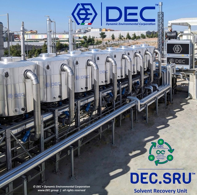
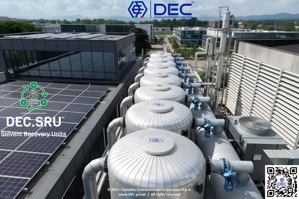
Solvent Recovery Systems (SRS), employed in solvent-based manufacturing processes, control air emissions of solvents (VOCs Volatile Organic Compounds and HAPs, Hazardous Air Pollutants from solvent-laden air or vapor), have high recovery rates of up to 99%, compliance with strict regulations, and significant cost savings by saving up to 90% on solvent costs, have an essential role in circular economy
Solvent Recovery (DEC.SRU™) • benefits
Apart from its environmental advantages, the Solvent Recovery (DEC.SRU™) offers compelling economic benefits by enabling the recovery and direct reuse of solvents. Solvents play a vital role in various manufacturing processes, and their efficient use is crucial for cost-effective production. By allowing for the direct reuse of recovered solvents, the DEC.SRU™ significantly reduces the need for new solvent purchases.
The cost savings achieved through solvent recovery contribute to an impressive Return on Investment (ROI). Manufacturing facilities adopting the Solvent Recovery (DEC.SRU™) can experience a substantial reduction in operational costs related to solvent procurement.
DEC is offering several decades of experience in design and installation of the most technically advanced and efficient vapor phase activated carbon solvent recovery systems.
DEC.RSG™ – activated carbon solvent recovery, TSA inert gas (nitrogen, N2) regeneration;
The ultimate solution in VOC emission control technologies. This advanced process leverages nitrogen to regenerate activated carbon, capturing solvents like ethyl acetate and ethanol with precision, slashing emissions, and enhancing sustainability. This cost-effective, eco-friendly technology excels in industries like packaging and chemicals.
Solvent Recovery Units, based on activated carbon adsorption, hot inert gas (N2, Nitrogen) regenerated, are using a core technology which has been proven in thousands industrial applications, treating variable volumes of gaseous effluent (typically 5.000 ÷ 1.000.000 Nm³⁄h); the regeneration of the adsorption media (activated carbon) is using Nitrogen as desorption media. This process is the ideal choice and the top performer when dealing with variable SLA volumes and variable (low-medium-high) concentrated VOC streams (mono and multi-solvent).
With hundreds of successful applications across diverse industries and continents, DEC.RSG™ tackles both mono-solvent and multi-solvent systems, delivering direct recovery of anhydrous solvents with zero process water discharge.
SRU RSG™ • challenging solvent recovery made possible
Azeotropes, where solvents and water mix inextricably (binary and ternary – e.g. acetates and alcohols), often pose a recovery challenge: DEC.RSG™ allows the direct recovery with a no compromise purity. With its ability to tackle azeotropes and various miscibility challenges, DEC.RSG™ solution is used in a wide range of industrial applications.
The DEC.RSG™ process also represents the solution for the recovery of problematic solvents (due to their volatility, flammability, or reactivity), which are deemed “NOT RECOVERABLE” or “DANGEROUS”: Typical application, is the recovery process of ketones (such as MEK – methylethylketone).
SRUs (Solvent Recovery Units) that utilize a nitrogen-regenerated TSA (Temperature Swing Adsorption) cycle are highly regarded for their robust design and sustained performance. This regeneration method contributes significantly to their durability and extended operational lifespan, making them a reliable choice for long-term solvent recovery applications. Their ability to consistently perform over prolonged periods minimizes downtime and reduces overall maintenance requirements.
The Technology Readiness Level (TRL) of DEC SRUs equipped with DEC.RSG™ process reached a high level of maturity, classified nowadays as TRL 9 (actual system proven in operational environment, according to ISO 16290:2013): the DEC.SRU™ technology is commercially available and has been proven to work effectively in real-world applications.
the solvent recovery process (SRU RSG™) • how it works?
The fundamental principle governing solvent recovery units is adsorption, most commonly utilizing activated carbon. The typical process unfolds in several stages:
|
Stage |
Process |
Description |
|
1 |
Filtration |
Removes particulate matter from the solvent-laden air (SLA) stream, preventing equipment fouling and ensuring optimal downstream-process performance. |
|
2 |
Cooling |
Reduces the temperature of the vapor stream to increase the activated carbon’s adsorption capacity for solvent molecules and improve adsorption efficiency. |
|
3 |
Adsorption |
The DEC.SBC™ static concentrator uses activated carbon with a highly porous structure and large surface area to adsorb VOCs and solvents. The SLA stream passes sequentially through a series of adsorbers, where solvent molecules are captured. The purified air is then discharged through the flue-gas stack (FGS). |
|
4 |
Regeneration |
Once saturated, the activated-carbon beds are regenerated through an in-situ Temperature Swing Adsorption (TSA) cycle. Hot inert nitrogen desorbs the captured solvents from the activated-carbon surface, preparing the carbon for reuse. |
|
5 |
Condensation |
The regeneration gas containing the desorbed solvent vapors is cooled, causing the solvents to condense into liquid form for collection, reuse or further processing. |
|
6 |
Dehydration |
Water—typically originating from adsorbed humidity—is removed from the recovered solvent mixture using molecular sieves, ensuring the required solvent purity. |
|
7 |
Distillation |
When the recovered stream contains multiple solvents or requires further purification, distillation separates the components according to their different boiling points. This produces purified solvents suitable for direct reuse in industrial processes. |
solvent recovery (SRU RSG™) • hydrolysis minimized, recovery maximized
DEC.RSG™’s “dry” Nitrogen-based desorption process ensures a negligible impact from hydrolysis reactions, safeguarding solvent integrity and purity for unprecedented recovery efficiency.
direct anhydrous recovery of solvents
DEC.RSG™ units can be equipped with DEC’s exclusive gas-phase pre-dehydration process, based on DEC’s exclusive selective desorption algorithm (DEC.PHD™): this innovative process offers the advantage of directly recovering a mixture of solvents with an extremely low water content, without the drawbacks of condensing / freezing important quantities of water, delivering outstanding energetic advantages and avoiding waste-water (contaminated by solvents) disposal or additional treatment, minimizing operational and environmental impact.
solvent recovery (SRU RSG™) • best-in-class energy efficiency
Efficient DEC.ERS™ (Energy Recovery Systems) are available, to lower operating costs (OPEX): check DEC.ULP™ (Ultra-Loop) modules, for more details.
DEC.RSG™ with DEC.ULP™ (Ultra-Loop) modules delivers unmatched operational and maintenance cost savings compared to any other technology on the market: up to a 30% reduction in O&M costs compared to traditional solvent recovery methods.
solvent recovery (SRU RSG™) • simplicity meets power: expert performance, without complexity
DEC SERVICE remotely monitors your SRU, ensuring optimal performance and freeing your resources for other priorities. This seamless remote support (DEC.HDS™) allows you to run the SRU efficiently with minimal operator involvement.
solvent recovery (SRU RSG™) • choose from our Smart Modular or Custom-Built Systems
DEC Solvent Recovery Units (SRUs) are available in both skid modular layout (DEC.SRU_SMS™ • Smart Modular Systems, pre-built and pre-tested at our workshops) or in full customizable version (DEC.SRU_CBS™ • Custom Built Systems, with on-site erection).
DEC.RSV™ – activated carbon solvent recovery, TSA steam (H2O) regeneration;
Steam regeneration (TSA) | DEC.RSG™ | DEC.SRU™
This technology which has been proven in thousands industrial applications (mainly for mono solvent systems), treating variable volumes of gaseous effluent (2.000 ÷ 1.000.000 Nm³/h); steam is used for the regeneration of the adsorption media (activated carbon), determining this process to be ideal for the recovery of non-water miscible solvents or for solvents which do not form azeotropic mixtures with water
The solvent recovery process: how it works?
The solvent recovery unit is formed by two or more activated carbon adsorbers, that alternate an adsorption phase with a regeneration one. The Solvent Laden Air (SLA), once it has been treated (filtered and conditioned), passes through the activated carbon bed of the adsorber that is in the adsorption phase: the carbon adsorbs the solvent and the air comes out cleansed. In the next phase a low-pressure steam flow, transferring heat to the activated carbon bed, desorbs the solvent. After it has been condensed, the solvent is sent to a static separator or distillation system to divide the water phase from the organic one.
|
Stage |
Process |
Description |
|
1 |
Filtration |
The solvent-laden air (SLA) is filtered to remove most particulate matter and prevent the adsorption bed in the static concentrator from becoming clogged. |
|
2 |
Temperature control |
The SLA temperature is regulated to achieve optimal adsorption conditions. The target temperature varies according to the solvents being removed and the required adsorption efficiency. |
|
3 |
Adsorption |
The SLA is passed through the static concentrator, where the activated carbon adsorbs the solvents through its large surface area and variable porous structure. |
|
4 |
Regeneration |
Once an activated-carbon adsorber becomes saturated, it is taken offline and regenerated in situ. Low-pressure steam transfers heat to the activated-carbon bed, desorbing and removing the captured solvents. |
|
5 |
Condensation |
The desorbed solvents are condensed in a heat exchanger and collected in a recovery tank. |
|
6 |
Separation |
The condensate is processed through a static separator or distillation system to separate the aqueous phase from the organic phase. |
|
7 |
Reuse |
The recovered solvents can be returned to and reused in the production process. |
choose from our Smart Modular or Custom-Built Systems
DEC Solvent Recovery Units (SRUs) are available in both skid modular layout (DEC.SMS™ • Smart Modular Systems, pre-built and pre-tested at our workshops) or in full customizable version (DEC.CBS™ • Custom Built Systems, with on-site erection).
DEC.RTV™ – activated carbon solvent recovery, T+VSA inert gas (nitrogen, N2) vacuum regeneration;
DEC.RTV™ | DEC.VRU™
This process is based on activated carbon adsorption, with a combined desorption process, by hot inert gas (N2, nitrogen) and vacuum regeneration (T+VSA process). The Vacuum Regenerated Solvent Recovery Units are the ideal VOC treatment technology for recovering solvents for low SLA volumes, ideally with steady medium-high concentrated VOC streams, discharged from storage tanks, vents, ships, railcars or truck tankers.
Solvent recovery systems, based on activated carbon adsorption, vacuum regenerated, are treating variable volumes of gaseous effluent (typically 500 ÷ 15.000 Nm³/h); the regeneration of the adsorption media (activated carbon) is made under vacuum [coupling different processes as TSA (thermal swing) + VSA (vacuum swing), under hot N2 (nitrogen)]
The solvent recovery unit is composed by two or more activated carbon adsorbers which alternate the adsorption and regeneration phase. The Solvent Laden Air (SLA), once treated (filtered and conditioned), passes through the activated carbon bed of the adsorber that is in the adsorption phase: the carbon adsorbs the solvent and the air deriving from this process is cleansed. In the next phase, desorbing the solvent under high vacuum starts.
Thanks to an efficient solvent condensation system, the recovered product is sent back to production tank(s). Non-condensable stream is recycled back to adsorption system. We must consider that water comes from the partial adsorption of humidity in the flow to be treated: systems for correction of relative humidity (DEC.RHC™) could be implemented for particular process conditions. Further recovered VOC drying processes may be applied.
Advanced safety and fire prevention, detection and suppression systems are available as options.
DEC Solvent Recovery Units (SRUs) are available in both skid modular layout (DEC.SMS™ • Smart Modular Systems, pre-built and pre-tested at our workshops) or in full customizable version (DEC.CBS™ • Custom Built Systems, with on-site erection).
DEC.RSC™ – solvent recovery, direct condensation.
This process uses a condenser to cool the solvent-laden gas stream. The cooled gas stream then condenses the solvent, which is collected in a receiver. Direct condensation is a simple and effective process that is well-suited for a variety of solvents.
The efficiency of direct condensation depends on the following factors:
- The boiling point of the solvent
- The concentration of the solvent in the gas stream. The higher the concentration, the more efficient the process.
- The cooling capacity of the condenser
Once condensed, the recovered solvent can be reused without further treatment or further processed through DEC.ADM™ dehydration modules (e.g. to separate water from humidity) and/or through a DEC.DST™ distillation unit.
Depending on the type of solvent(s) to be recovered and the level of VOC emission requested at the stack of the system, a disposable activated carbon filter (DEC.AFU™) or a concentration system (DEC.XBC™) may be required for further VOC abatement, prior to exhaust at stack.
DEC.RSC™ • simple direct condensation
Direct condensation is a relatively low-cost and safe process: the main costs associated with direct condensation are the cost of the condenser and the cost of the energy used to cool-down the SLA gas stream.
DEC.RSC™ • cryogenic condensation, liquid nitrogen – N2
The cryogenic condensation solvent recovery process is ideal for low flow rates (typically < 2.000 Nm³/h) and high concentrations of VOC ( > 0,5% vol).
Using liquid nitrogen as the refrigerant, the cryo-condensation process is designed to cool the effluent in a process stream to very low temperatures, thanks to the use of advanced heat exchangers, which are characterized by high fractionating capacities of vapors and gases.
The stream effluent is separated by decreasing the vapor pressure as a function of the vapor/liquid and vapor/solid equilibrium. The VOC is recovered for reuse in the process (directly or after distillation) or as a fuel (DEC.WTE™ – Waste To Energy module), while the nitrogen is cycled back into the process for purging and blanketing operations.
The cryo-condensation units are usually very compact, requiring a relatively small footprint, and are skid mounted (DEC.SMS™ – Smart Modular Systems), lowering installation and start-up costs. The system design minimizes moving parts, reducing maintenance and repair.
Thermal Oxidizers – direct, regenerative and catalithic
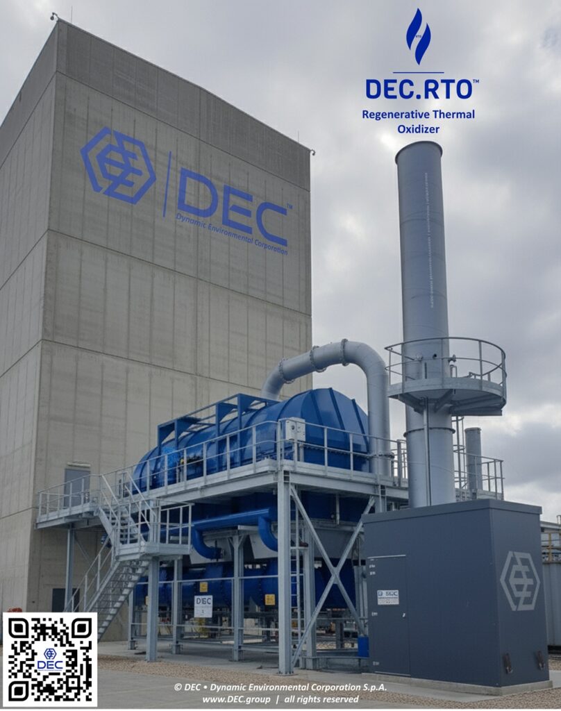
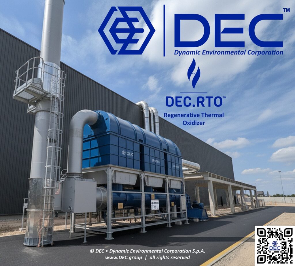
In cases where the VOC stream is too complex to be recovered, or if the quantity of solvents is not enough to make recovery economically feasible or sustainable; a thermal oxidation technology may be the only viable option to safely and effectively destroy VOCs. The decision of which VOC abatement technology to use should be made on a case-by-case basis, taking into account the specific characteristics of the VOC stream and the environmental and economic considerations, always keeping the circular economy drivers in mind when making decisions about VOC abatement.
Thermal Oxidizers are APC air pollution control devices commonly employed in chemical industries: DEC.XTOs™ operate by decomposing hazardous gases, at high temperatures (typically around 590°C to 980°C), releasing the resulting gases into the atmosphere.
DEC.XTO™ thermal oxidizers primarily target Volatile Organic Compounds (VOCs) present in industrial air streams: these pollutants, typically hydrocarbon-based, undergo thermal combustion, converting them into carbon dioxide (CO2) and water (H2O) through chemical oxidation.
DEC offers a full spectrum of thermal oxidizers tailored to your VOC emission control needs, including:
- RTO™ • Regenerative Thermal Oxidizer
- CTO™ • Catalytic Thermal Oxidizer
- DTO™ • Direct-fired Thermal Oxidizer
thermal oxidation | oxidizers • oxidation reaction
VOC laden air from the process is drawn into the oxidizer system with the help of the fan system, then through the combustion chamber(s); the VOCs are heated up to the oxidation temperature and transformed in gases, following this reaction:
VOCs (CxHyOz) + O2 + thermal energy = CO2 + H2O + (HEAT)
The excess heat, when available, is usually recovered to pre-heat the SLA stream, in order to reduce the need of additional “thermal energy” (typically provided through gas CH4 – methane or LPG, or H2 or alternatively or in combination with electric heaters); if producing extra heat through oxidation of solvents, an energy recovery system shall be foreseen (typical applications are ranging from heating up air for dryers, steam production, heat transfer fluid heating, water heating – industrial or sanitary, etc.).
thermal oxidation | oxidizers • GHG and by-products
An oxidizer is handling the transformation of the pollutant(s) into different products, with a reduced environmental impact. However, it is important to consider the resulting GHG emissions, when selecting a VOC oxidizer; the amount of GHGs generated by a thermal oxidizer depends on the type of VOCs being treated, its quantity, the needed quantity of fuel to be added for sustaining the oxidation reaction and the selected oxidizer process configuration.
Any oxidizer will have to deal with all or most of the following issues:
- VOCs emission (= non complete oxidation);
- CO2 emission (= GHG, possible taxation);
- CO emission (= GHG, non complete oxidation);
- NOx emission (= nitrogen oxides, as a result of N2 presence);
- N2O emission (= nitrous oxide);
- Dioxin and Furan emission (as a result of possible chlorinated compounds and operating temperatures);
- High temperature emission (as a result of non complete thermal energy recovery).
These emissions contribute to climate change and should be taken into account when assessing the overall environmental impact of the system.
Oxidizers typically require a significant amount of energy to operate: if this energy comes from non-renewable or carbon-intensive sources, this aspect will further contribute to environmental degradation and offset any of the potential benefits of VOC emission reduction.
DEHYDRATION SYSTEMS FOR SOLVENTS – molecular sieves, liquid and gaseous phase

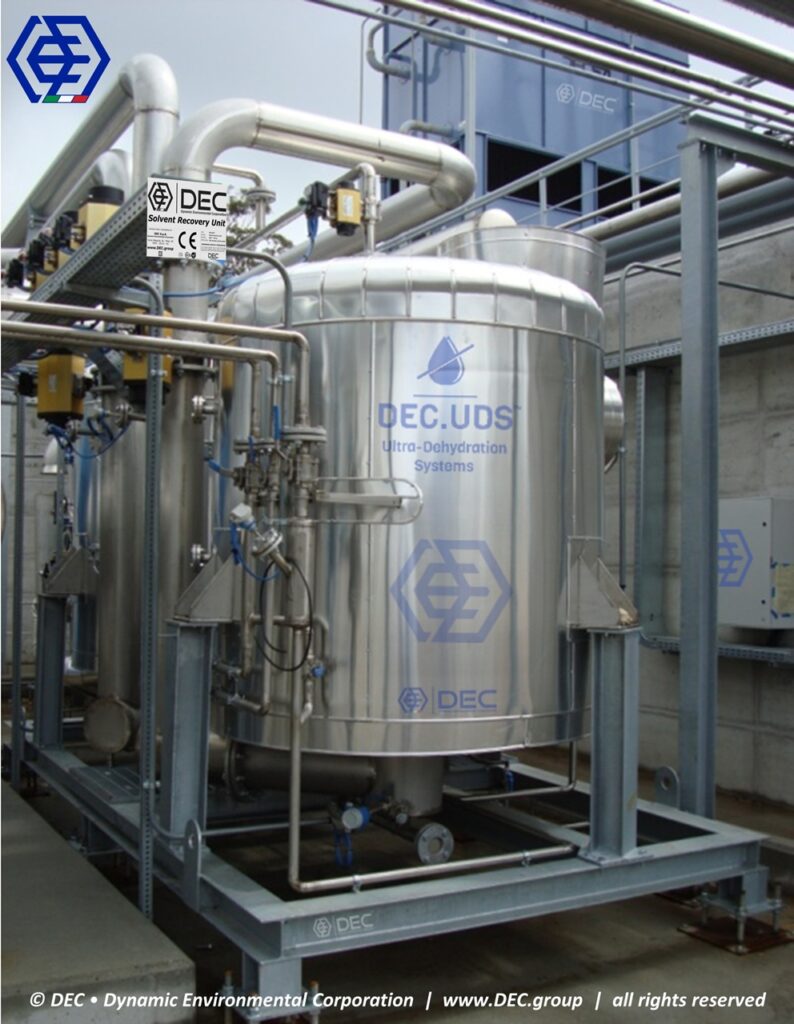
industrial dehydration systems for activated carbon Solvent Recovery Units
DEC.ADM™ industrial dehydration systems are coupled with an activated carbon Solvent Recovery Units (DEC.SRU™), as an optional add-on module or as a retrofit.
Engineered to optimize performance while minimizing energy consumption by moisture removal, ADM™ systems ensure quality of the recovered solvent, and meet stringent quality standards. The modular design adapts to unique needs of pharmaceuticals, flexible packaging, or chemical manufacturing industries.
The streams of Ethyl Acetate, Isopropyl Acetate, Ethyl Alcohol, Isopropyl Alcohol (common solvents used in flexible packaging) will be recovered fully dehydrated, even exceeding fresh virgin solvent specs (i.e. Ethyl Acetate urethane grade, suitable for high performance solvent-based lamination – i.e. retort sterilizable).
Key features
|
Feature |
Specification |
|
High efficiency |
Advanced technology removes moisture from the recovered solvent rapidly and effectively, reducing downstream processing requirements. |
|
Customizable design |
The modular configuration enables seamless integration into existing solvent recovery units (SRUs) and allows future capacity expansion. |
|
Energy savings |
Optimized systems minimize energy consumption and operating costs without compromising output. |
|
Robust construction |
Durable construction ensures reliable, long-term performance, even in demanding operating environments. |
|
Compliance readiness |
Designed to meet applicable industry safety and quality standards. |
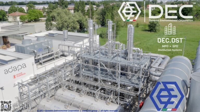
DISTILLATION SYSTEMS – batch and continuous
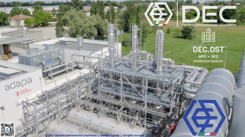
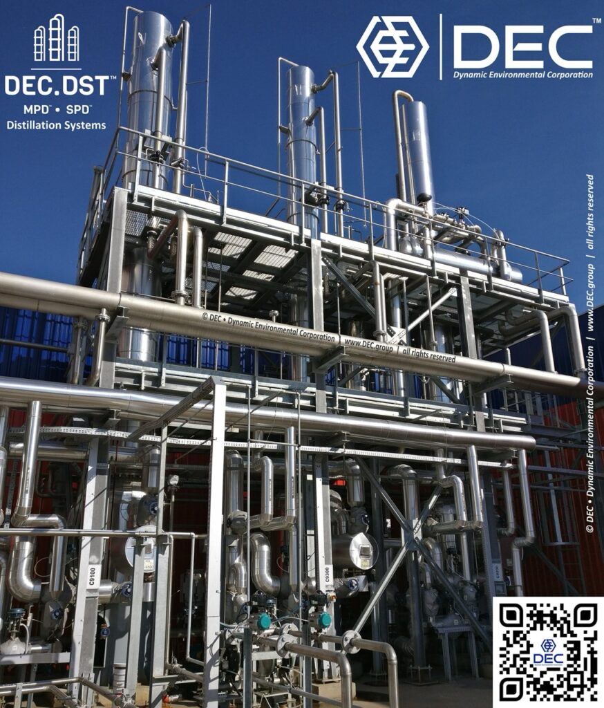
Distillation is the most widely-used method of separating fluid mixtures on a commercial scale, it is thus an important part of many processes industries, including the packaging, chemical, oil and gas, and pharmaceutical sectors.
DEC.DST™ industrial solvent distillation systems are specifically designed to break down solvent mixtures into their individual components. This process allows for the recovery and reuse of valuable solvents, while also generating high-purity products for various applications.
We provide tailored solutions for industrial applications, focusing on optimizing column performance and ensuring high-purity product output. Whether you’re seeking cost-effective systems for ethyl acetate or ethanol recovery from flexible packaging operations or need to troubleshoot existing units for azeotropes recovery in converting industries, our expertise ensures a seamless process.
Our energy-efficient distillation methods, coupled with our deep understanding of packed columns and fractional distillation, can significantly reduce your operational costs and environmental impact.
DEC.DST™ • distillation systems • batch (MPD™) | continuous (SPD™)
The distillation systems are coupled with the solvent recovery plants, in order to separate the mix of “raw” recovered solvents. If the solvents are soluble (totally or partially) with water, in order to increase the overall efficiency, the use of our DEC.ADM™ dehydration systems may be considered, so to remove the residual water content in the raw recovered solvent (coming from the humidity), before feeding the distillation plant.
DEC.DST™ • distillation systems | configuration
The following processes are available (stand-alone or multi-effect configuration):
- DST-a™ – atmospheric distillation;
- DST-p™ – pressure distillation;
- DST-v™ – vacuum distillation;
- DST-e™ – extractive distillation;
- DST-r™ – reactive distillation;
- DST-re™ – hybrid reactive-extractive distillation.
DEC.DST™ • Enhanced Approach to Distillation Process Optimization
|
Feature |
Specification |
|
State-of-the-art process simulation |
Utilizes advanced process-simulation tools to accurately predict and optimize distillation performance. |
|
Comprehensive data integration |
An internal database connected with leading research institutes and universities provides access to current scientific advances and empirical data. |
|
In-house experimental validation |
The dedicated DEC LAB enables practical experimentation and validation, bridging the gap between simulation and real operating conditions. Results are therefore supported by measurable experimental outcomes rather than relying solely on theoretical projections. |
This integrated approach, coupled with our extensive engineering expertise, empowers us to deliver “true and realistic” results, precisely tailored to each client’s unique requirements.
DEC.DST™ • case-specific optimization and product quality
We understand that every distillation process is unique. Therefore, we conduct thorough, case-by-case analyses to determine optimal operating parameters, including:
|
Feature |
Specification |
|
Column design |
Precise determination of the number of columns required for efficient separation |
|
Stage and packing optimization |
Accurate calculation of the theoretical equilibrium stages, translated into the appropriate selection of DEC.SPK™ structured packing and its optimum height |
|
Product optimization |
Process parameters tailored to maximize product purity, yield and energy recovery |
DEC.DST™ • stringent product quality standards for direct reuse
Recognizing the critical importance of product quality for reuse in the productive cycle, we ensure that distilled products consistently meet stringent requirements:
|
Feature |
Specification |
|
High purity |
Achieves the required product-purity levels through precise process control, including an inline gas-chromatography process analyzer |
|
Maximum efficiency |
Optimizes energy utilization while minimizing process waste |
|
Effective energy recovery |
Recovers and reuses energy to reduce operating costs and environmental impact |
By combining advanced simulation, experimental validation, and a deep understanding of distillation principles, we provide our clients with optimized solutions that deliver exceptional product quality and operational efficiency.
ENERGY RECOVERY SOLUTIONS
DEC.ERS™
Energy recovery is the process of capturing and reusing waste energy from different industrial processes to generate a different energy or use it to power other processes within the same plant. This includes low-grade heat sources like exhaust gases, steam condensate, and waste liquids.
As energy costs continue to rise and environmental regulations become stricter, energy recovery is becoming increasingly important. In the future, we can expect to see more and more energy recovery being used in the chemical and petrochemical industries.
- ULP™ • Ultra-Loop™
- HRM™ • Heat Recovery Modules
- WTE™ • Waste to Energy
- THR™ • Thermal Heat Recovery
- WHR™ • Waste Heat Recovery
Energy Recovery Solutions are valuable tools which can help industrial plants to reduce their energy consumption, greenhouse gas emissions, and operating costs: by investing in DEC.ERS™ technologies, plants can improve their environmental performance and bottom line.
LEL CONTROL AND RECIRCULATION SYSTEMS
Advanced Flow Optimization
DEC.AFO™
When you’re planning to implement a VOC (Volatile Organic Compound) emission control system, whether it’s a solvent recovery unit or a thermal oxidizer), one crucial element often overlooked but holding significant potential for efficiency gains is Advanced Flow Optimization (DEC.AFO™).
In today’s landscape of ever-increasing energy costs, businesses in the flexible packaging and converting industries – those utilizing rotogravure, flexographic printing, lamination machines, coating and lacquering lines – are actively seeking and evaluating energy saving technologies to bolster their competitiveness in the global market. Optimizing airflow within your production and emission control systems is a key strategy in achieving substantial energy reductions and operational cost savings.
DEC.AFO™ • available configurations
DEC offers a suite of advanced flow optimization solutions under the DEC.AFO™ umbrella, designed to maximize the efficiency and effectiveness of your VOC emission control investments:
|
Technology |
Specification |
|
DEC.FRS™—LEL Automatic Flow Recirculation System |
Automatically adjusts airflow according to the Lower Explosive Limit (LEL) of the VOCs present. When conditions are safe, treated air is recirculated, reducing the volume requiring heating or cooling. This provides significant energy savings, enhances safety and reduces fugitive emissions. |
|
DEC.ISC™—Integrated Suction Control |
Provides precise, dynamic control of suction at individual emission points, ensuring that only the necessary airflow is extracted. This prevents energy losses caused by over-ventilation, improves capture efficiency and reduces the load on the emission-control system. |
|
DEC.PTE™—Permanent Total Enclosures and Fugitive Emission Control |
Contains VOC emissions directly at the source, minimizing the air volume requiring treatment and improving the overall efficiency of the emission-control system. Preventing the widespread dispersion of fugitive emissions contributes to safer and more environmentally responsible operations. |
STATIC, ROTARY, FLUIDIZED BED CONCENTRATORS
DEC.XBC™
DEC.XBC™ VOC concentrators are a useful tool for reducing solvent emissions from industrial processes: these units are a type of air pollution control device that uses a static, rotary or fluidized bed to remove low concentrations of solvents from large volumes of air.
VOC concentrators are the ideal choice for low solvent concentrations: they are designed for situations where the concentration of solvents in the air is between 0,1 and 2,5 grams per cubic meter (g/m3).
DEC.XBC™ available configurations
VOC concentrators are available in different configurations, depending on the process conditions and deliverables:
- DEC.SBC™ • Static Bed VOC concentrators
- DEC.RBC™ • Rotary Bed VOC Concentrators
- DEC.FBC™ • Fluidized Bed VOC Concentrators
DEC.XBC™ working principle
|
Process stage |
Specification |
|
Adsorption |
The concentrator uses vessels filled with an adsorbent material, such as activated carbon, zeolite, molecular sieves or polymers. As the polluted solvent-laden air (SLA) passes through the vessel, solvents are captured by the adsorbent. The resulting clean air is then discharged or recirculated into the production process. |
|
Regeneration |
Once saturated with solvents, the adsorbent is regenerated using hot air. The captured solvents are desorbed and concentrated into an air stream that is approximately 10–30 times smaller than the original stream. |
|
Further treatment |
The concentrated solvent stream can be treated efficiently in a separate VOC-treatment system, such as a solvent recovery unit or thermal oxidizer. |
DEC.XBC™ benefits
- Effective for treating large volumes of air, with low solvent concentrations;
- Concentrates solvents for efficient further treatment;
- Allows for efficient recovery or destruction of solvents, reducing CAPEX and OPEX of the final VOC treatment system.
NITROGEN GENERATORS
SOLVENT STORAGE AND DISTRIBUTION
DEC.SSD™
DEC.SSD™ is a modular ecosystem designed to optimize industrial processes involving hazardous chemicals. It integrates multiple specialized components, each addressing specific safety, operational, or environmental needs. The system minimizes risks like leaks, fires, and vapor emissions while enhancing process efficiency.
Key components of the DEC.SSD™ ecosystem, each tailored to address specific safety and operational needs:
|
System |
Specification |
|
DEC.SST™—Solvent Storage Tanks |
Purpose-built for the safe containment of flammable solvents, inks and resins. The tanks comply with international safety standards, providing secure storage while minimizing the risks of leaks, spills and vapor emissions. |
|
DEC.TBS™—Tank Blanketing System |
Maintains a protective layer of inert gas—typically nitrogen—above the solvent surface to prevent vapor formation, oxidation and fire hazards. |
|
DEC.MBX™—Solvent Mixing Box |
Provides precise blending of solvents, inks or resins according to specific formulation requirements, optimizing process efficiency. |
|
DEC.LDS™—Leakage Detection System |
Uses sensors to detect vapors generated by leaks in solvent-storage areas through Lower Explosive Limit (LEL) monitoring. |
|
DEC.SGD™—Static Ground Detection |
Detects and controls static-electricity build-up during solvent handling and transfer, helping to prevent fires, explosions and equipment damage in flammable environments. |
|
DEC.WSN™—Water Sprinkler Nozzles |
Protects SST_AST™ tanks containing flammable solvents. Sprinkler nozzles positioned around the tank provide complete coverage and cool the tank if exposed to fire. The system is activated by a fusible link or another fire-detection sensor. |
|
DEC.SDS™—Solvent Distribution System |
Safely transfers solvents, inks and resins from DEC.SST™ storage tanks to points of use. The system prevents leaks, spills and contamination while maintaining operational efficiency. |